

Home . About . GPS . Downloads . Business . Partners . Contact . Family . AVL . Links . History . AsOnTV . Forum


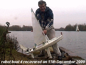
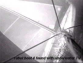
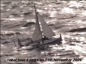 Snoopy Sloop 4 sank below the waves on 19th November 2009.
We heard over the radio from Snoopy: "Not Again !!!".
After three weeks we found him using a rescue boat with towed underwater TV camera and a winch.
After many days of trying, in murky water, we eventually
raised Snoopy On 15th December.
 Almost all the electronic bits still worked, despite their spending
almost four weeks in Bray Lake, under twelve feet of water.
The new year was spent in preparing our new boat: Snoopy Sloop 5.
On the left is boat 5 under construction.
Our very first boat, which also sank on
it's maiden voyage, is near the window. Boat 4, raised from Bray Lake,
was filled with foam so it should not sink again.
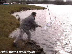
On 25th February 2010: boat 4 got to sail again, and boat 5 had it's maiden voyage.
Boat 5 uses the same sails
as boat 4 which is a standard IOM class model (International One Metre). In the picture,
boat 4 has the smallest (storm) sails on it, and boat 5 has the largest sails.
 Boat 5 is longer, at 5 feet (1.52 metres) and has a double keel. Most of the hull is now foam ! :-)
 Here is the much heavier, Snoopy Sloop 3, originally intended to be Robin's first boat capable
of going to sea.
 Snoopy Sloop 3 may still sail, when the wind is strong enough, but now the much smaller
Snoopy Sloop 4 has the limelight. We are experimenting with alternative vane-rudder steering systems,
and are already getting respectable speeds of over 3 knots.
Robin's new PICAXE - based controller can control two servos from the iPAQ Pocket PC, but also switch power and act as a watchdog timer. More reliability and less power consumed means less solar panels and/or more adventurous voyages :-)

 We have squeezed our existing electronics into an International One Metre (IOM) sized boat. Robin has
been picking the brains of friends and local sailing clubs.
Thanks to Eric, Robin was given an IOM hull and
two rigs including masts and sails, which were used to make Snoopy Sloop 4 above.
There will need to be changes (e.g. that keel will snag weed) but it will be interesting to see what strong winds such a lightweight approach, with storm rig, might survive.
Robin has also invested in 5 channel 2.4GHz radio control gear, just in case he is invited to test a robot boat on places other than Bray Lake. One channel is used to switch between radio and iPAQ computer control. If switched to radio control, the left stick can control the vane-rudder and main sail. Also, the right stick can over-ride the vane-rudder, and switch on an electric motor - for if and when the computer has thrown a wobbly :-)

 The #3 hull is the front 1 metre of a wind surf board with a concrete keel and lead weighing about 7 kg.
It has three slim hulls.
We started with simple radio control speed tests using the new wing-sail-float.
We have lots more computer-sailing tests yet to do.
The earlier Snoopy Sloop 2 (either side) seemed to manage between about 1.5 to 2 knots in a 10 knot breeze. In April we sailed Snoopy Snoop 2 with a simple tethered wing-sail-float made of solid foam, and tried out the onboard wireless TV camera for the first time. We called it "wobble cam", and you will see why ! :-)
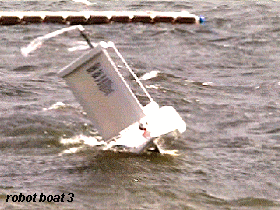
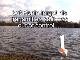
Before this, on Friday 27th February, we sailed the modified Snoopy Sloop 2 for the first time. This, our second boat, had undergone a major refit, with wider but hopefully faster hull and a wing sail. But silly Robin forgot to bring one of the radio control transmitters - but worse still, he still launched the boat - which then sailed randomly around Bray Lake, before hitting the island. Luckily a galliant young lady came to the rescue, and Snoopy survived to sail another day :-)
|

|

|
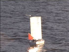
We returned on Thursday 5th March - this time with all the equipment, and in a 10 knot breeze, the new Snoopy Sloop 2 seemed to perform well. Look at those first two frames below: it looks as if it can sail within 45 degrees of the wind, although lots of tests have yet to be done. Near the end you will see it sailing backwards, then the "floppy rudder" doing it's work to pull the boat round. On the next sail, maybe we will try the onboard wireless TV camera. - see our Red Kites page.
|

|

|


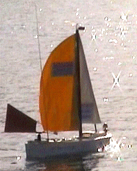 Here on the left, you see Snoopy Sloop 2, with
conventional sails, in November 2008.
Below, under "recent thoughts" is our first boat, Snoopy Sloop (1) before it was "christened" below the surface of Bray Lake and then had extensive modifications such as a heavier keel and larger hull.
On the right you see the wing sail being constructed. Snoopy Sloop 2 is of similar size as Snoopy Sloop 1, still less than 1.2 m in length and with a mast of less than 80cm high - so it can be easily transported in the back of an estate car. All the electronics are the same, including iPAQ computer, servo control electronics, and PMR radio for "talking" details to shore. Both boats have two radio control systems: one for "emergency use" that controls rudder and electric motor, and the "primary" one, to control a change-over switch, between the computer and radio control to operate the two servos: vane-rudder and sail winch.
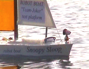
 The main differences in Snoopy Sloop 2 are in a sleeker hull and the vane-rudder system which is now at the stern. This means
a linkage is used to reverse the direction between vane and rudder. The "recovery" radio control steering
is also mechanically linked into the same rudder, and all electronics is powered by a common 5v NiMHd battery
supply. Solar panels are used to extend battery life a little.
By late November '08 we have switched over to use of the new Snoopy Sloop 2 boat, with the original as our "backup" for spares. We are now into adjustments for things like improved tacking into wind, speed, and continue tests of the autopilot software.
Oh yes - Snoopy now has a more prominent position for his role as "lookout" on the bow :-)
We are now thinking more seriously about what our first sea-going boats may look like. Robin is still at the stage of thinking about the basic design principles, building techniques and products to use. Ideally, he would like to see small sea-going boats, of maybe no more than a metre long, yet able to sail almost anywhere* in the World in all weather conditions, for an unlimited time of many months or years. Cost is obviously also an important factor. Robot boats of only a metre long might not be as fast as boats of 3 or 4 metres, but they might be more survivable, and there would certainly be less problems of "health and safety" concerning where they are allowed to sail - particularly coastal waters, or busy traffic lanes like the English Channel. A smaller boat is obviously much easier to transport, launch and recover - eventually :-)
 Current "hot topics" include what sort of servo assemblies to use - able to withstand occasional
complete imersion in sea water, and the expected rigours of rough sea conditions.
The vane-rudder
is the essential servo, but a wing-sail is also probable. I'm grateful to the University of Wales Team
for their brilliant idea of using magnetic coupling, so that the servos might be completely enclosed.
They told us of the small, 1 inch diameter disc magnets from K&J Magnetics in the USA
and details are
here.
I got 8 for tests (cost me about 90 GBP) and we seem to get about 2 kg-cm torque, through perhaps 90 degrees, even with
a gap of 5mm. A much smaller gap down to 1mm maybe doubles this. This should certainly be enough for
the vane-rudder on our small boats, and may be enough for a wing sail. We gear the 1T servo (see below)
with a 2:1 pulley onto the wing sail, and so this doubles the servo torque. Our wing sail is currently less than 0.5 square
metres, being 72cm wide by 67cm high. It may end up being much smaller after more testing on Bray Lake.

 Another major benifit of this magnetic coupling is protection of the servos from heavy mechanical jolts.
e.g. if a wave hits the vane-rudder or wing sail. The vane or sail can move, to "ride the punch", but should
quickly return to the correct position. 1 or 2 kg-cm torque is comfortably lower than the 6 kg-cm rating
of our S125 servo mentioned below.
I've now found a suitable water-tight box: the RP1065 from Maplin at less than 4 GBP each. These are made from ABS, measure 85mm x 80mm x 55mm and include a rubber gasket. The two magnets are seperated by approximately 5mm.
We got the low cost (19 GBP) S125 1T 2BB J 360 degree servos from Hightorque UK. We currently use these for both vane-rudder and wing sail, using a 2:1 pulley to gear down for the required 180 degrees. On the right you see that the larger 3.5-Turn servo also fits in the box. This Hitec HS-785HB is rated up to 11 kg-cm torque, but the magnetic coupling limits this to 1.5 kg-cm. If we used 7:1 gearing, to reduce the 3.5 turns down to 180 degrees for the wing-sail, we should obtain a useful torque above 10 kg-cm.
Next question is what to use for the 7:1 gearing ? spur gears ? timing chain ? Any ideas ?
How else to water proof a servo ? See the u-tube video here. But we would expect to have an outer box and bigger sealed bearing.
It looks like SPOT could be our deep-ocean tracker, although we would expect to use GPS/GSM in addition, while within a few miles of the coast. The SPOT satellite tracker is on www.findmespot.com and here but we will need to modify it. GPS/GSM trackers are on Robin's chase page. We are using solar panels from solarpanelsonline.co.uk and details are here . Each panel is 13cmx13cm and delivers up to typically 250mA into our 5v 4 cell NiMHd packs. We currently estimate we will need at least 10 of these.
* almost anywhere: although probably not through ice-fields or polar regions in winter, with no light for solar panels. Maybe up and down some large rivers or canals, but not across land :-)
 June and I managed to meet some of
the main players of this Trans-Atlantic race, at the lake in Austria,
during our
holiday.
Thanks to the trip to Breitenbrunn, to see robot boats,
we also saw Vienna and the "singing toilets" :-)
The design that we are working on is much simpler than the more obvious solution that we first thought of back in May 2008. My GPS Software for the Pocket PC has been extended to include a simple autopilot function. Anyone is welcome to use it, although I am sure others will already have their own, much better, GPS based solutions.
 The picture on the left shows our fleet of toy boats that were used to test simple vane-rudder solutions.
These tests on Bray Lake went well, and our later tests involve a radio controlled servo between vane
and rudder. This can also be computer-controlled.
On the upper right is Snoopy, standing on our 2 ft radio controlled test boat, recently baptized - see "baptism of Snoopy" below.
 The next picture shows the updated boat, with more hull volume (expanding foam) and heavier keel (4 kg of lead).
Our latest thoughts are that an iPAQ computer, with GPS and servo controller, will be running software
which will do the following:
If we were only thinking John's "Team Joker" boat sailing the Atlantic, we might get away without worrying about the effect of the tide.

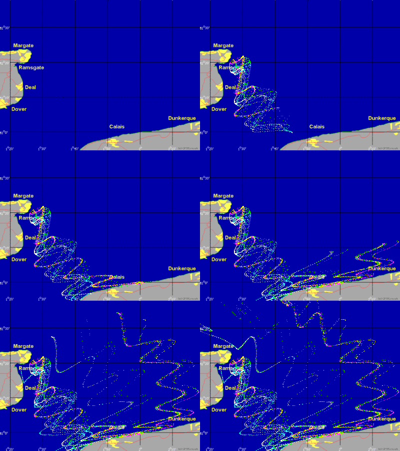 However, since John might begin with attempting to sail around the Isle of Wight, or crossing the Channel,
ignoring the tide could result in our autopilot doing rather silly things. Imagine crossing the Channel
from Dover to Calais with a nice steady wind blowing in a particular direction: to the east. Imagine
what happens if the tide is also taking us south. Our simple autopilot logic would wrongly think this is due to
the wind direction, blowing south-east, and would trim the boat to "fight the tide". It would be better
to accept the drift and sail the boat directly towards its destination.
The animated picture on the right is from one of our more detailed "GPS bottle" pages here. It shows the results of our modelling the path of several bottles due to the effect of wind and tide. Tides in the channel might be faster than our small boat could sail.
There are several solutions to this problem including the obvious one that we thought of back in May: don't rely on just the GPS, but use other sensors such as weather vane and compass to measure the wind direction directly. But of course, more sensors give more opportunity for something to fail. Another solution would be to model the tides within the AutoPilot.
The solution we are testing is simple: the AutoPilot does a regular test to measure the drift due to tide. This need only be done infrequently such as every 30 minutes - depending how rapidly the tide may be changing due to time and where the boat is. For the test, the boat is pointed directly into wind with the sail flapping (or "flogging"), and after this test, lasting perhaps only one minute, the drift is known, and used in later calculations of wind direction and vane-rudder settings.
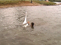
Here are some piccys from our home video shot on 14th July, showing a very eventful "baptism" of Snoopy...

|

|

|

|

|
|

|

|
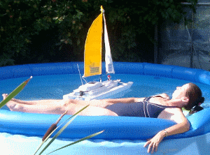 Lots of small but important things were corrected on "Snoopy Sloop", our 2 ft test platform - including a heavier keel
, better thrust angle of motors (for recovery), better sealing - including the hatch, and bouyancy bags
- so next time it did not sink to the very bottom ! :-)
Many Thanks to James, for borrowing a wet-suit and diving in to (eventually) find the boat deep on the lake bottom, and recover it. Strange as it may seem, after drying out, all the electronics, including two radios and servos, work perfectly. Later that night I was able to test the little electronics card from Klaus in Germany - and (of course) they worked first time - so now my GPS auto-pilot can control the vane-rudder servos (and any other servos such as main sheet). Of course, I made sure the boat was checked out better before our next launch - in June's swimming pool ;-)
 Recent
beta
versions of GPSS for the Pocket PC include the AutoPilot function.
you do not need the special electronics such as those seen here, to test the AutoPilot software. You would need to start by getting the software working with a GPS on something like an iPAQ, after looking at the Pocket PC page, and take advantage of free registration and support from Robin - including making sure you have the latest AutoPilot version. A few extra sound files are needed, downloaded from PPCAUTOP.EXE.
The AutoPilot is switched on with the [AP] button on the "maintenance" page (under spanner button). You can also set the initial wind direction here. The AutoPilot runs every 60 seconds and updates the vane-rudder position, to steer towards the destination. It also adjusts the direction of the wind based on the boats actual movement.
It also speaks all the information, for use during testing: either walking about on dry land with your GPS, or over a PMR radio when on the water and too far away for you to hear the computer speaking. Direction is in degrees, clockwise from north.
"Attention... this is the robot boat autopilot for Snoopy..." (configurable with AUTOP1.WAV)
"latitude 51.39699 degrees North, longitude 0.65993 degrees West"
"changing destination to Georgetown, Saint Vincent" (waypoints defined in AUTOP.TXT)
"The AutoPilot says the boat has moved a distance and direction of: 30 metres, 090"
"The speed is 1.2 knots"
"Wind direction is 90 degrees" (from west, blowing due east).
"Destination 085" (direction needed towards destination)
"AutoPilot calculated direction error is 5 degrees" (away from direction needed)
"Vane-Rudder angle is 5 degrees" (new vane-rudder setting to correct course sailed)
"wind is from the port side"
For those like John intending to drive an actual vane-rudder servo, they will need to wire the output of the computer's RS232 serial port to an SSCII servo controller, via a protocol convertor such as that seen here from Klaus. This is a "hardware workaround" to the Microsoft OS not allowing more than 7 data bits to be sent to the SSCII - which needs 8 data bits (255 = start of message, 0 = servo number, 0..254 = servo position) GPSSppc sends 127, 0, 0..126 which is converted by the card supplied by Klaus.
The AutoPilot now operates four servos, which some people may wish to use:
 Sounds used by the AutoPilot can be replaced or augmented by recording WAV files. e.g. the
message at the begining of a voice radio transmission can identify the boat. Intermediate destinations
such waypoints can be recorded to give them a particular name. There are standard features in GPSSppc
that can be switched on, such as giving the Expected Time of Arrival at the destination. The picture
on the right shows a PMR radio, set to be voice-operated, giving ship-shore communications
during trials.
If a file with name AUTOP.TXT, similar to that below, is included in the GPSSppc folder, then the AutoPilot reads it for information such as changing the destination when reaching a new waypoint. This can be used to avoid the boat running aground on known islands, or making better use of the expected trade wind patterns.
A typical AUTOP.TXT is as follows, the first line being a comment:
AUTOP.TXT is used to configure the autopilot in GPSSppc. See www.gpss.co.uk/autop.htm
8
00.0000 000.0000,99999,13.2750 -61.1190,Georgetown St Vincent,STVINCEN.WAV, default destination
32.8000 -16.5000,60,33.7000 -18.4000,avoid Madeira,DESTINAT.WAV, avoid running aground
51.3970 -0.66000,0.01,51.3973 -0.6598,up the road,DESTINAT.WAV, test waypoint near Robin's home

51.3973 -0.6598,0.01,51.3970 -0.66000,Home,HOME.WAV, return back to Robin's home
51.5001 -0.6907,0.01,51.4990 -0.69200,Middle of Lake,MIDDLEOL.WAV,Bray Lake first waypoint
51.4990 -0.69200,0.01,51.5000 -0.6894,Clubhouse,CLUBHOUS.WAV,return to Bray Lake Clubhouse
51.5000 -0.69500,0.20,51.5000 -0.6894,Clubhouse,CLUBHOUS.WAV,protect from rest of lake
51.4975 -0.69000,0.20,51.5000 -0.6894,Clubhouse,CLUBHOUS.WAV,protect from rest of lake
45
275
1
0
Above lines are data. These lines document the file format.
8 - number of waypoints of route
waypoint lat/lon of circle, radius of circle in km, destination lat/lon, name, WAV file, comment
The smallest circle covering the position causes the destination to change.
So the default destination for the whole World in Georgetown in St Vincent.
Same mechanism is used to cause diversions to avoid running aground.
45 - how close can the boat sail into wind as degrees from directly into wind.
275 - full travel of the vane-rudder servo. Mid position is directly downwind.
1 - minutes between checks on GPS position and computer control of boat.
0 - minutes between a check on drift due to tide. 0 if none.
 Hi Folks ! Here are a few of my early thoughts on this daft idea from John :-)
John and I chatted about his transatlantic model boat project, and shortly after dropped an SSC03A servo controller in to me to test. I have, and it seems to be just what we need. My messy test setup is in the piccys below.
First the simple concept for an autopilot that would steer a boat, or maybe an aircraft. The software would obviously do very different things. e.g. 'planes don't need to tack against the wind, but they do have other problems to solve !
These are the bits I think we need as a minimum:
"Keep it Simple Stupid" must obviously be our motto, although I suspect the design will become slightly more complicate as it solves the obvious problems of reliability, power, us knowing where it is, etc, etc, etc. e.g. some may ask "is the flux gate compass needed ?": unfortunately I think the answer is "yes" because the Autopilot will probably need reliable information on which way the boat is pointing - not easy from the GPS alone on a choppy sea. The good news is that such products already exist, and will provide the compass heading on the same signal line as the position, velocity, etc. Searching on google will find solutions, but for now I'm assuming something like the Garmin etrex summit, providing the usual $GPRMC NMEA sentences, but also one like this: $HCHDG,101.1,,,7.1,W*3C - the 101.1 is magnetic heading and the 7.1 is magnetic variation.
I did a bit of soldering, and threw a first little test program called AUTOP together.
The picture below shows the bits: the lead from the yellow Garmin etrex (on the left) comes in from the right and plugs, via the RS-232 Y- splitter, into the COM1 9-way D (male) socket on my old Laptop. It could have plugged in direct, but the splitter is needed to drive the SSC03A just below the etrex. From the etrex, the signal is on pin 2 and signal ground on pin 5. To the SSC03A, the signal is on pin 3. The SSC03A could also plug direct into the Laptop COM1. You also see four old r/c servos that I had to hand for tests.
On the right you see my old HP iPAQ - maybe a suitable computer. My problem there is that I need a spare connector, like the one you see near it, to get at those RS232 pins on the iPAQ. However, I should be able to make use of more messy leads as a "temporary work-around" if and when I'm ready to try the iPAQ in a mobile test setup - maybe even on water :-)
below that picture you will see another, of what appears on the PC screen from AUTOP.EXE

Below you see what appears when you run AUTOP.EXE, which I put in the GPSS folder so it can use the same DLL as found in the GPSS Baseline on the download page. Clicking on [OPEN] will open the COM port and 4800 is the NMEA standard. Clicking on [SEND] will send these three bytes to the SSC03A which you will see described on www.pololu.com. I'm using the simple "Mini SSC II Mode" and this seems to work OK - even if GPS data is coming in. If you wire a GPS in to the same port, as I have, you will see GPS data coming in the box below. If you move one of the eight servo sliders, the approriate values are set up ready for [SEND].

The above is obviously only a simple test program. No point in doing more software if there is no suitable hardware to test it with. Now I think I need a flux gate compass combined with a GPS.
Thanks for the iPAQ plugs Jose :-)